Arduino: ESP32 Home automation (Simple On/Off control using MQTT)
We have built a home automation system using NodeMCU here. In this post we will try to replicate same system using ESP32. We will connect couple of LEDs to ESP32 and control those LEDs from a WebApp (The WebApp is integrated into this blog, scroll down to see!!).
Environment requirements:
- ESP32
- Arduino IDE environment to program ESP32
- Arduino libraries : PubSubClient,ArduinoJson 5.13.1 (if you haven’t already installed it , you can install it from Sketch->Include library->Manage Libraries)
- mqtt broker , if you don’t have one you can use eclipse Paho broker for experimentation (host: iot.eclipse.org , port : 1883, it is a free and open broker)
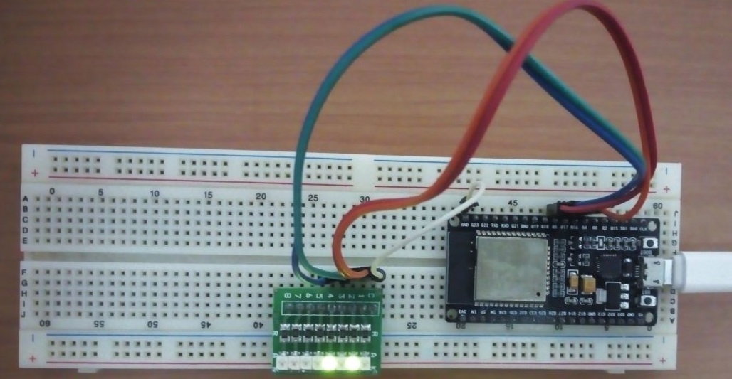
- couple of LEDs and breadboard to see the output
Solution Approach :
MQTT will be used to transport messages between ESP32 and client application. All the messages are JSON encoded.We already know how to connect ESP32 to Access point and MQTT broker from this post. You can check this post by Nuno Santos to know more about parsing JSON messages using ArduinoJson library.

ESP32 will listen on the following channel for messages
/ic/ha/to/esp32/gpio/
Expected JSON message is format is as follows
{
  "switches": [
    {
      "status": false,
      "id": 1,
      "lable": "GPIO 4"
    },
    {
      "status": false,
      "id": 2,
      "lable": "GPIO 5"
    },
    {
      "status": false,
      "id": 3,
      "lable": "GPIO 16"
    },
    {
      "status": true,
      "id": 4,
      "lable": "GPIO 17"
    }
  ]
}
we have an array called “switches”, each item in this array is a switch with three fields. status indicates whether IO is high(true) or low(false). id is used to map each switch to GPIOs of the ESP32. We need to manipulate the status filed of respective switches to control it for example to make GPIO 4 HIGH and remaining all GPIOs low, we need to send following message on the MQTT channel
{
  "switches": [
    {
      "status": true,
      "id": 1,
      "lable": "GPIO 4"
    },
    {
      "status": false,
      "id": 2,
      "lable": "GPIO 5"
    },
    {
      "status": false,
      "id": 3,
      "lable": "GPIO 16"
    },
    {
      "status": false,
      "id": 4,
      "lable": "GPIO 17"
    }
  ]
}
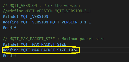
PubSub client default max message length is 128, since our message much bigger than that, we need to increase it to 1024. You can find the setting in PubSubClinet.h file (~\Documents\Arduino\libraries\pubsubclient\src). Remember to change it back to 128 once you are done with the testing (otherwise other arduino boards with lesser RAM may not work properly)
Code:
First we will connect to given access point (change the ssid, password to connect to your network). By default ESP32 will connect to eclipse open mqtt broker. if you have MQTT broker change the mqtt_server,mqtt_port (if the broker is protected by user name and password you need to mention them in MQTT_USER, MQTT_PASSWORD). Once ESP is connected to network it will try to initiate connection with broker and subscribe to the channel “/ic/ha/to/esp32/gpio/“. In main loop we have nothing much to do , we simply call loop method of pubsub client.
When a new message is received pubsub will call you callback method with channel name and message. we need to parse the received JSON and switch the GPIO accordingly.
How To Test:
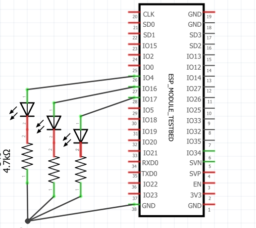
Connect LEDs to GPIO4,5,16,17 with a 4k7 resistor
Copy the above code to Arduino IDE and Upload the code to ESP32 and open serial console. Console will show connected message if it is connected to MQTT broker (if it prints any error code, check you network, MQTT settings in the code)
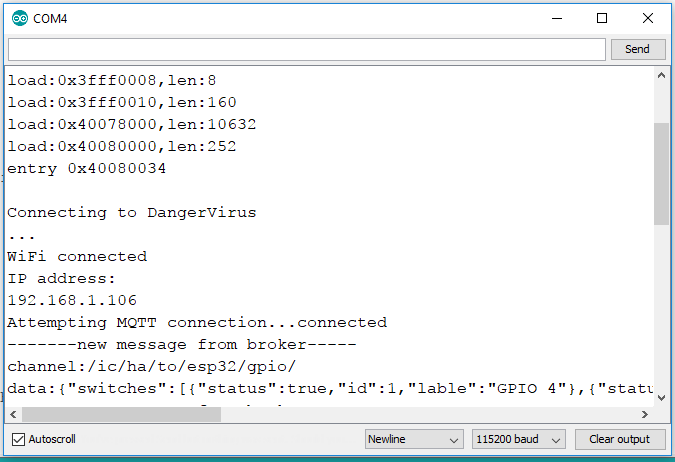
Now ESP32 is ready to receive messages from MQTT broker, click on “Connect” below (if you are using a different MQTT broker provide those details in the respective fields), you will see four buttons (if the button is in blue means OFF,green means ON). Click the button to control the LEDs.
———————————————————–
———————————————————–


Hello,
I tried your example on ESP32( WROOM32) with change of paths libraries only because have duplicate:
#include
#include
…..
But have error:
Archiving built core (caching) in: C:\Users\Nelu\AppData\Local\Temp\arduino_cache_450829\core\core_espressif_esp32_esp32_FlashMode_qio,FlashFreq_80,FlashSize_4M,UploadSpeed_921600,DebugLevel_none_898f9e38ebae302494d0e119be95335d.a
sketch\mqtt3leds.ino.ino.cpp.o:(.literal._Z10setup_wifiv+0x10): undefined reference to `WiFi’
sketch\mqtt3leds.ino.ino.cpp.o:(.literal._Z10setup_wifiv+0x24): undefined reference to `WiFiClass::begin(char*, char const*)’
sketch\mqtt3leds.ino.ino.cpp.o:(.literal._Z10setup_wifiv+0x28): undefined reference to `WiFiClass::status()’
sketch\mqtt3leds.ino.ino.cpp.o:(.literal._Z10setup_wifiv+0x2c): undefined reference to `WiFiClass::localIP()’
sketch\mqtt3leds.ino.ino.cpp.o:(.literal._Z9reconnectv+0x34): undefined reference to `PubSubClient::connected()’
sketch\mqtt3leds.ino.ino.cpp.o:(.literal._Z9reconnectv+0x38): undefined reference to `PubSubClient::connect(char const*, char const*, char const*)’
sketch\mqtt3leds.ino.ino.cpp.o:(.literal._Z9reconnectv+0x3c): undefined reference to `PubSubClient::publish(char const*, char const*)’
sketch\mqtt3leds.ino.ino.cpp.o:(.literal._Z9reconnectv+0x40): undefined reference to `PubSubClient::subscribe(char const*)’
sketch\mqtt3leds.ino.ino.cpp.o:(.literal._Z9reconnectv+0x44): undefined reference to `PubSubClient::state()’
sketch\mqtt3leds.ino.ino.cpp.o:(.literal._Z5setupv+0x14): undefined reference to `PubSubClient::setServer(char const*, unsigned short)’
sketch\mqtt3leds.ino.ino.cpp.o:(.literal._Z5setupv+0x18): undefined reference to `PubSubClient::setCallback(void (*)(char*, unsigned char*, unsigned int))’
sketch\mqtt3leds.ino.ino.cpp.o:(.literal._Z4loopv+0x0): undefined reference to `PubSubClient::loop()’
sketch\mqtt3leds.ino.ino.cpp.o:(.literal.startup._GLOBAL__sub_I_ssid+0x8): undefined reference to `WiFiClient::WiFiClient()’
sketch\mqtt3leds.ino.ino.cpp.o:(.literal.startup._GLOBAL__sub_I_ssid+0xc): undefined reference to `PubSubClient::PubSubClient(Client&)’
sketch\mqtt3leds.ino.ino.cpp.o: In function `setup_wifi()’:
C:\Users\Nelu\Documents\Arduino\mqtt3leds\mqtt3leds.ino/mqtt3leds.ino.ino:109: undefined reference to `WiFiClass::begin(char*, char const*)’
C:\Users\Nelu\Documents\Arduino\mqtt3leds\mqtt3leds.ino/mqtt3leds.ino.ino:109: undefined reference to `WiFiClass::status()’
C:\Users\Nelu\Documents\Arduino\mqtt3leds\mqtt3leds.ino/mqtt3leds.ino.ino:109: undefined reference to `WiFiClass::localIP()’
C:\Users\Nelu\Documents\Arduino\mqtt3leds\mqtt3leds.ino/mqtt3leds.ino.ino:109: undefined reference to `PubSubClient::connected()’
sketch\mqtt3leds.ino.ino.cpp.o: In function `reconnect()’:
C:\Users\Nelu\Documents\Arduino\mqtt3leds\mqtt3leds.ino/mqtt3leds.ino.ino:109: undefined reference to `PubSubClient::connect(char const*, char const*, char const*)’
C:\Users\Nelu\Documents\Arduino\mqtt3leds\mqtt3leds.ino/mqtt3leds.ino.ino:109: undefined reference to `PubSubClient::publish(char const*, char const*)’
C:\Users\Nelu\Documents\Arduino\mqtt3leds\mqtt3leds.ino/mqtt3leds.ino.ino:109: undefined reference to `PubSubClient::subscribe(char const*)’
C:\Users\Nelu\Documents\Arduino\mqtt3leds\mqtt3leds.ino/mqtt3leds.ino.ino:109: undefined reference to `PubSubClient::state()’
sketch\mqtt3leds.ino.ino.cpp.o: In function `setup()’:
C:\Users\Nelu\Documents\Arduino\mqtt3leds\mqtt3leds.ino/mqtt3leds.ino.ino:109: undefined reference to `PubSubClient::setServer(char const*, unsigned short)’
C:\Users\Nelu\Documents\Arduino\mqtt3leds\mqtt3leds.ino/mqtt3leds.ino.ino:109: undefined reference to `PubSubClient::setCallback(void (*)(char*, unsigned char*, unsigned int))’
sketch\mqtt3leds.ino.ino.cpp.o: In function `loop()’:
C:\Users\Nelu\Documents\Arduino\mqtt3leds\mqtt3leds.ino/mqtt3leds.ino.ino:109: undefined reference to `PubSubClient::loop()’
sketch\mqtt3leds.ino.ino.cpp.o: In function `ArduinoJson::JsonBuffer::createObject()’:
C:\Users\Nelu\Documents\Arduino\mqtt3leds\mqtt3leds.ino/mqtt3leds.ino.ino:109: undefined reference to `WiFiClient::WiFiClient()’
sketch\mqtt3leds.ino.ino.cpp.o: In function `_GLOBAL__sub_I_ssid’:
C:\Users\Nelu\Documents\Arduino\mqtt3leds\mqtt3leds.ino/mqtt3leds.ino.ino:109: undefined reference to `PubSubClient::PubSubClient(Client&)’
collect2.exe: error: ld returned 1 exit status
exit status 1
Error compiling for board ESP32 Dev Module.
Have any idea for fixing?
Thanks.
Hi Ion,
seems some problem with include statements, compiler is complaining that WiFi.h is not included. You should be having all three imports for the script to work
609/5000
Hello,
First of all I would like to congratulate you, I am learning a lot!
When compiling this code, I get the following message:
“exit status 1
‘StaticJsonBuffer’ was not declared in this scope ”
Could you tell me how to declare it?
I also received a message from multiple libraries of WiFi.h, but I have noticed that this error occurs almost always, when it gives a problem with my codes, I believe it is not a serious problem in itself, because other codes using WiFi.h have run well and I’ve also tried everything to remove them, until I reinstall everything from scratch, but the damn ones persist. (I.e.
Thank you again!
I again, but now to bring good news.
I managed to solve the problem I was facing, after searching, I decided to check the version of the libraries I was using, and when checking ArduinoJson, I realized that it was a beta, I downgraded it and BINGO, the code compiled.
Thanks again for making your knowledge available and teaching us in a direct and didactic way.
Glad it helped you
Hello for the message ‘StaticJsonBuffer’ was not declared in this scope it’s due to the library ArduinoJson. you must downgrade your version to 5.13.1 and it will be OK.
Thanks, I updated the blog to include the version.
Helo,
thanks for this code.
Its work on my ESP, but what i must sent on
mqtt Topic? For on and off the pins?
Do you like make this code with PWM and fade with brake?
Thanks
Hello,
script works fine – can you add:
MQTT_SERIAL_PUBLISH_CH
if the ESP32 received the changes, send its the acknolage to mgtt/openhab..
It is possible?
Tanks
it should be possible, I will try add it