ESP-IDF : Lets Control Servo Using ESP32
ESP32 has many features/APIs that are not available with ESP8266. Few my favorites are timers API and LED control API.
It can do lot fun stuff with servos. There many ways to generate to generate the PWM signal required by the servos. You can use the MCPWM API specifically designed for generating pwm signals or you can use the LED control API. In this post will see how write a servo sweep program using LED control API of ESP32. Though the LED control API is designed for controlling RGB leds, we can also use this for generic PWM signal generation.
Short introduction about the LED PWM peripheral
LEDC Pheripheral:
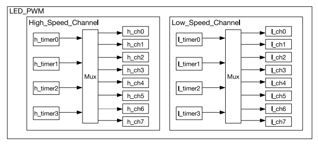
The LED PWM peripheral is backed by 4 high speed timer and 4 low speed timers. These timers are independent of the generic 64 bit timers (Its wonder to me, how ). Each timer can generate two PWM channels. So in total we have 8 high speed PWM channels and 8 low speed PWM channels.
LED Control API
ESP-IDF provides LED control API which uses the LED PWM peripheral in ESP32. The LED control API is backed by the hardware, its kind of wrapper around the LED PWM hardware, using which we can easily manipulate the registers. This way we don’t need to bother about the underlying hardware and different registers we need to use to control the hardware.
The API is fairly simple to use, first we configure the timer that we want to use, then attach the configured timer to a channel. The output of the channel can be mapped to a GPIO
    ledc_timer_config_t timer_conf;

    timer_conf.bit_num = LEDC_TIMER_15_BIT;

    timer_conf.freq_hz = 50;

    timer_conf.speed_mode = LEDC_HIGH_SPEED_MODE;

    timer_conf.timer_num = LEDC_TIMER_0;

    ledc_timer_config(&timer_conf);
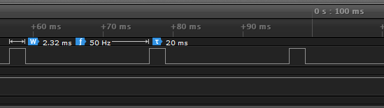
above snipped shows how to configure TIMER 0 in HIGH SPEED MODE at 50Hz frequency. Bit number specifies the precision of the generated PWM. For 15 bit precision, you can set the duty any where between 0 – ((2**bit_num)-1) . Lowest precision you can set is 10 bit and heighest is 15 bit.
Once the timer is configured , we need to configure a channel to use this timer
    ledc_channel_config_t ledc_conf;

    ledc_conf.channel = LEDC_CHANNEL_0;

    ledc_conf.duty = duty;

    ledc_conf.gpio_num = 16;

    ledc_conf.intr_type = LEDC_INTR_DISABLE;

    ledc_conf.speed_mode = LEDC_HIGH_SPEED_MODE;

    ledc_conf.timer_sel = LEDC_TIMER_0;

    ledc_channel_config(&ledc_conf);
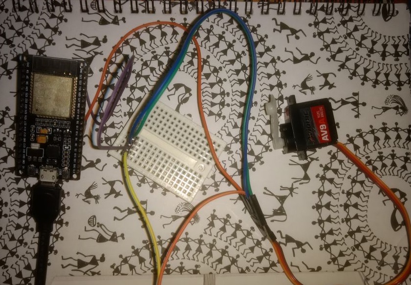
This snippets sets the channel 0 to use timer 0. We are specifiying to use GPIO 16, Our servo signal line should be connected to GPIO16. The ESP32 signal voltage level is 3v3 , I didn’t face any problem driving 5v servo signal line with the GPIO directly, don’t connect ESP32 3v3 to servo VCC line, take the 5v required by the servo from external voltage source (you should connect together the external power supply GND with the ESP32 GND) .
By changing the duty value, we can set the servo at different positions.
You can calculate the resulting PWM duty cycle using the following formula
duty cycle = ( ledc_conf.duty/ ((2**bit_num)-1) ) * 100
ledc_conf.duty is the duty we are setting
full servo sweep code is available in git repo


thank you a lot
it’s fantastic, when you start studying and can find these tutorials on different topics