Getting started with 2*16 Character LCD
In this post we are going learn how to interface LCD (Liquid Crystal Display) with Atmega8. LCD’s are very common in embedded systems like Coffee machines, Weighing machines etc.,
Generally these LCD have 16 pins.
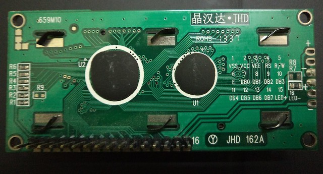
The numbering starts from left to right in the above picture. The left most pin is VSS and right most pin is LED-
Pin1 (VSS) : Connect ground of your 5V Supply to this pin
Pin2 (VDD) : 5V Supply
Pin3 (VEE) : This is the contrast voltage pin. We should connect this pin via a potentiometer if we want to change the
contrast of the LCD module. For default contrast this pin has to be connected to ground pin. But I strongly recommend to have a potentiometer.
Pin4 (RS) : Register select, By using this we decide whether the information we are passing on the data bus is data or a command. When this line is low, bytes transferred to the display are treated as commands and bytes read from the display indicate its status. By setting RS line high, character data can be transferred to and from the module.
Pin5 (R/W) : This is Read/Write line. Low logic on this line indicates write to the LCD module and high indicates read from the LCD module.
Pin6 (E) : Enable, This pin is used to initiate the actual transfer of commands or character data between the module and data lines. When we are writing on the display, data is transferred only on the high to low transition of this signal. However, when reading form the LCD, data will be available shortly after the low to high transition and remain stable until signal falls low again
Pin7 to Pin14 (D0 to D7): Data lines, Normally there are two type of display modes and they are 4-bit mode and 8-bit mode.
8-bit mode: In this mode we will use 8 data lines (D0-D7) to transfer the data. That is one byte will transferred at a time.
4-bit mode: In this mode we will use only 4 data line(D4-D7) to transfer the data. One byte will be transferred as two nibbles(1 nibble=4 bits).
Mode selection purely depends on the number of IO lines available in your micro-controller. If you have plenty enough to support 8-bit mode, you can use 8-bit mode. But by using 4-bit mode, we can save 4 IO lines. In this post I will explain 4-bit mode.
Pin15 (LED+) : This pin is the positive terminal of back light LED. Connect it to 5V supply.
Pin16 (LED-) : This pin is negative terminal of back light LED. Connect it to the GND
LCD Command set:
|
Command |
Binary |
Hex |
|||||||
| D7 | D6 | D5 | D4 | D3 | D2 | D1 | D0 | ||
| Clear Display | 0 | 0 | 0 | 0 | 0 | 0 | 0 | 1 | 01 |
| Cursor Home | 0 | 0 | 0 | 0 | 0 | 0 | 1 | x | 02 or 03 |
| Character Entry Mode | 0 | 0 | 0 | 0 | 0 | 1 | I/D | S | 04 to 07 |
| Display on/off & Cursor | 0 | 0 | 0 | 0 | 1 | D | U | B | 08 to 0F |
| Display/Cursor Shift | 0 | 0 | 0 | 1 | D/C | R/L | x | x | 10 to 1F |
| Function set | 0 | 0 | 1 | 8/4 | 2/1 | 10/7 | x | x | 20 to 3F |
I/D: 1=Increment ‘,0=Decrement
S: 1=Display shift on ,0= Display shift off ‘
D: 1=Display on , 0=Display off ‘
U: 1=Cursor underline on, 0=Cursor under line off ‘
B: 1=Cursor blink on, 0=Cursor blink off ‘
D/C: 1=Display shift, 0=cursor move
R/L: 1 = Right shift, 0 = Left shift
8/4: 1=8 bit interface’,0=4 bit interface
2/1: 1= 2 line mode, 0 = 1 line mode’
10/7: 1= 5*10 dot format, 0 = 5*7 dot format’
‘ = indicates initial setting
Now we have all the information to write our first program for LCD. We will write a small program that will display iCircuit on LCD
Functions required:
lcd_clrscr() //to clear the display
lcd_puts() //to write strings
lcd_putc() //to wrote character data
lcd_cmd() //to write command buytes
lcd_gotoxy() //to navigate to different positions in LCD
lcd_init() //to initialize the LCD with the required settings.
we need to decide the IO mapping also.we need 4 data lines and 3 control lines. In total we need 7 IO’s
D4-D7 : PD4-PD7
RS : PB0
E : PB1
R/W : PB2
Now we can implement the functions one by one.
#include<avr/io.h>
#define F_CPU 16000000ul
#include<util/delay.h>

#define e_low PORTB&=~(1<<PB1)
#define e_high PORTB|=(1<<PB1)
#define rw_low PORTB&=~(1<<PB2)
#define rw_high PORTB|=(1<<PB2)
#define rs_low PORTB&=~(1<<PB0)
#define rs_high PORTB|=(1<<PB0) void lcd_busy() //to check LCD readiness to receive commands from controller { // we will wait here until LCD is ready to receive the commands from controller e_low; rs_low; //change the data lines to input mode DDRD&=0x0F; rw_high; //we are reading the data from LCD uint8_t data=0x80; while((data&0x80)==0x80) { e_high; _delay_us(20); data=(PIND&0xF0); e_low; _delay_us(20); e_high; _delay_us(20); data|=(PIND&0xF0)>>4;
      e_low;
     _delay_us(20);
   }
 DDRD|=0xF0; //make data lines as ouput
}

 void e_toggle()
 {
   e_high;
   _delay_us(10);
   e_low;
 }

 void lcd_write(uint8_t c,uint8_t rs)//rs 1 means data,0 means cmd
 {
    if(rs)
    {
      rs_high;
    }
   else
   {
     rs_low;
    }
   rw_low;//since we are writing

 //output high nibble first
 PORTD&=0x0F; //clear the data lines
 PORTD|=(c&0xF0);
 e_toggle();

 //ouput low nibble
 PORTD&=0x0F; //clear the data lines
 PORTD|=((c<<4));
 e_toggle();

 }

void lcd_putc(char c)
{
 lcd_busy();
 lcd_write(c,1);
}

void lcd_puts(char* str)
{
 uint8_t c;
 while ( (c = *str++) ) {
 lcd_putc(c);
 }
}

void lcd_cmd(char c)
{
 lcd_busy();
 lcd_write(c,0);
}
void lcd_clrscr()
{
 lcd_cmd(0x01);//clear data
 lcd_cmd(0x02); //set cusrosr to home
}

void lcd_gotoxy( uint8_t x, uint8_t y)
{
 uint8_t cmd=128+(64*y)+x;
 lcd_cmd(cmd);
}

void lcd_init()
{
 //initialize IO lines
 DDRD|=0xF0;
 DDRB|=0x07;
 _delay_ms(16);

 rs_low;  //by default the LCD will be in 8-bit mode, we need to bring it to 4 bit mode
 rw_low;
 PORTD&=0x0F;
 PORTD|=(0x20); //enable four 4 bit mode
 e_toggle();

 lcd_cmd(0x2C); //4 bit mode,2 line,5*10 dot format
 lcd_cmd(0x0E); //display on, cursor under line on
 lcd_cmd(0x01); //Clear display
}

int main()
{
 lcd_init(); //we need to call this function before doing any operation on LCD
 while(1)
 {
 lcd_puts("----iCircuit----");
 _delay_ms(5000); //5 sec delay, this is built in fucntion
  lcd_clrscr();
 _delay_ms(2000);
 }
}
Now we have all the functions to display some text on LCD. So build the program and burn to HEX file to Atmega8. Hurry Up!!


