DC motor speed control using chopper circuit

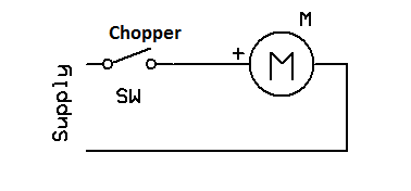
DC motor speed control is an important industrial application. There are several methods to control DC motor speed one of them is chopper circuit. This chopper circuit is simple square wave generator which can be easily built using 555.
Chopper circuit can be implemented in two ways
1.Constant frequency:
In this method we will keep the frequency constant and vary the duty cycle. This method is also know as PWM(Pulse Width Modulation) scheme.
2.Variable frequency:
In this method we keep either on-time or off-time constant and vary the frequency. This method is also know as Frequency modulation scheme.
Mostly in speed control circuits PWM method is used. So here I’ll implement PWM method.

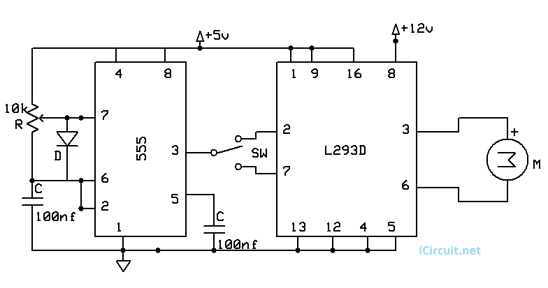
The 555 circuit provides 1.4 kHz square wave. The duty cycle (speed of the motor) of this wave can be changed by using the value of R which is a controlling resistor. L293D is used as driver circuit for DC gear motor. The switch SW is used to change the direction of the motor.


this is all i needed, this circuit! this thing works! thank you brother! cheers!