Interfacing controllers with TM1637
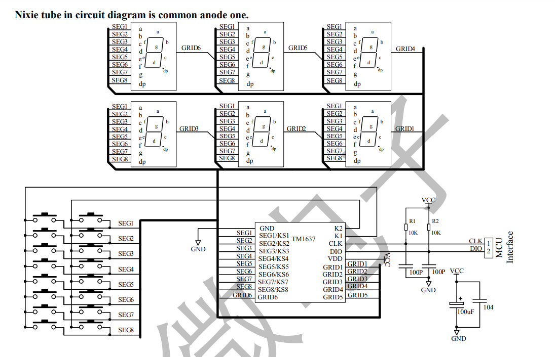
TM1637 is an inexpensive LED driver come keypad scanner. There are many 4 digit 7 segment displays in market that uses TM1637 LED driver. It can driver upto 48 LEDs (8 * 6 config) and can scan 16 keys (8 * 2 config). It has simple two wire communication protocol (clock and data lines), any controller with atleast two digital IOs can communicate with this driver.
The communication protocol is very similar to I2C but not same. If the host controller provides full access to the I2C hardware, then you may be able to use the I2C hardware to stream data to the driver instead of using bitbanging method.

Features
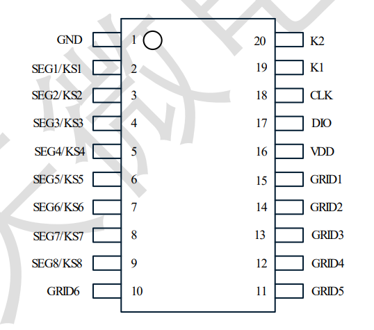
- 20 pin chip
- 8 * 6 LED control
- 8 * 2 Keypad
- works with board 3v3 and 5v supplies, support clocks speeds of upto 500 KHz
WIRE PROTOCOL
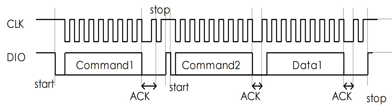
Pulling the Data line (DIO) down while the clock is high indicates start bit and pulling it up while the clock is high indicates stop bit. while sending data, the data line need to change its state when the clock is low, the chip will read the data line when the clock moves from low to high. When the communication is initiated the first byte will act as mode/data command which will tell the driver on how to interpret the incoming bytes.
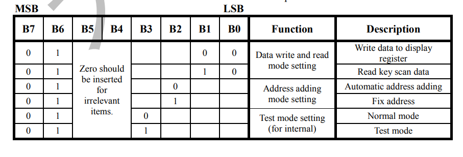
The driver has 6 8-bit display registers ( 0xC0- 0xC5 ) for holding state of each LED. Data can be set in each register individually(Fixed address mode) or can be written to the consecutive set of registers (Automatic address mode).
Fixed address mode
In fixed address mode, we need to send 3 bytes to write data to any one display register.
<mode/data command> <address> <display register data>
mode command tells the driver how interpret the incoming data. For example if we want to write 0x3F (represents decimal 0 on 7-segment display) to 0xC0 register (first display register), we need to send following byte stream on the wire.
0x44 0xC0 0x3F
Automatic address mode
In automatic address mode, we just send the first display register address, then send as many bytes as there are register from the given register offset. For example to write 1234 decimals to a 4 digit 7 segment display we need to send the following byte stream.
0x40 0xC0 0x06 0x5B 0x4F 0x66
Display control
The driver also lets us control the brightness of the display, it supports 8 levels of brightness. To set brightness we need to two bytes.
<mode/data command> <display command>
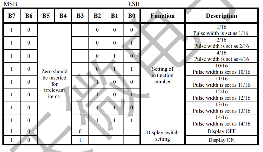
For example to set the display at ~62% brightness, we need to send following byte stream. The second byte values ranges from (0x88 to 0x8F).
0x40 0x8B
We can also switch off the display by sending following byte stream.
0x40 0x80
Code
following pseudo code describe how to send data to driver. Any controller that has 2 digital IOs can communicate with the display driver. There are three basic operations.
- send start bit
- send stop bit
- send a byte
all other operations can be described in terms these three operations.
void start() {
    setDataPin(0)
    sleep(CLK_CYCLE_DELAY)
    setClkPint(0)
    sleep(CLK_CYCLE_DELAY)
}

void stop() {
    setDataPin(0)
    sleep(CLK_CYCLE_DELAY)
    setClkPint(1)
    sleep(CLK_CYCLE_DELAY)
    setDataPin(1)
}


void writeByte(byte){
    for(int i=0;i<8;i++){
      setDataPin(byte >> i * 0x01)
      sleep(CLK_CYCLE_DELAY)
      setClkPint(1)
      sleep(CLK_CYCLE_DELAY)
      setClkPint(0)
      sleep(CLK_CYCLE_DELAY)
    }

    setClkPint(0)
    sleep(CLK_CYCLE_DELAY)
    setClkPint(1)
    sleep(CLK_CYCLE_DELAY)
    setClkPint(0)
    sleep(CLK_CYCLE_DELAY)
}

void writeDataCmd(cmd){
    start()
    writeByte(cmd)
    stop()
}

void sendByteStream(bytes,len) {
    writeDataCmd(0x44)
    start()
    for(int i=0;i<len;i++){
        writeByte(bytes[i])
    }
    stop()
}
The above code derived from this library.


