Remote PWM Control – NodeMCU and MQTT
In this blog we will see how to change PWM duty cycle of NodeMCU (PWM control) from a remote client. Our hard ware will be nodeMCU and on client side we will use an android app. We will use MQTT to transfer data between client and nodeMCU.
On nodeMCU side the flow is
- Connect to a WiFi
- Register with MQTT broker and start listening for messages on the specified channel
- If any message is arrived , analyze it and change the duty cycle accordingly (actually we are sending lua statements, so the NodeMCU will simply execute them)
You can have at most 6 PWM pins with maximum of 1 KHz frequency. The duty cycle can be specified with 10 bit precision ( 0 – 1023).
PWM Important functions:
pwm.setup(pin,frequency,duty)
pwm.start(pin)
pwm.stop(pin)
pwm.setduty(pin,duty)
pwm.getduty(pin)
pwm.setclock(pin)
pwm.getclock(pin)
We will be sending the pwm commands from client to the NodeMCU instead of sending only pwm data. We have already seen how to send code to NodeMCU here. On NodeMCU side same code will work.
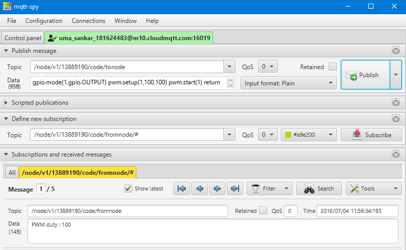
On client side you can use mqtt-spy or any MQTT client to send code snippets to the NodeMCU
Channel to send the code snippets
/node/v1/{chipid}/code/tonode
if you have any return statement in the code you sent , the return will appear in the following channel
/node/v1/{chipid}/code/fromnode
for example if you want to set the pin 1 with 100 Hz, 512 duty cycle you can send the following code snippet
gpio.mode(1,gpio.OUTPUT) pwm.setup(1,100,512) pwm.start(1) return "PWM duty : "..pwm.getduty(1)
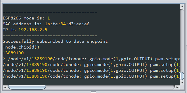
You can see the code snippets in the NodeMCU serial console.
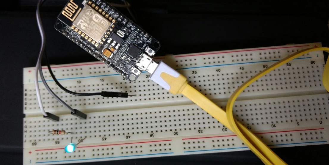
Following is the image of LED connected to GPIO 1, at duty cycle of 100
We can develop client apps for different platforms with GUI controls to manipulate the parameters.


All good content ! Keep it up.
Note sure why wifi mcu didn’t get attention of community, seems like the features on par with nodemcu