CircuitPython : Interfacing TM1637 with Circuit playground express
TM1637 is an LED driver chip that can also scan a keypad. It can drive 48 LEDs (8*6) and can read 8*2 keypad. In this post we will see how to control 4 digit 7-segment display with adafruit circuit playground express board using CircuitPython.
What you need
- Circuit playground express board
- TM1637 based 4 digit 7-segment display
- CircuitPython setup and few jumpers to connect 7-segment display with controller board
if your express board is not already loaded with circuitpython, see this post.
About TM1637 LED Driver
TM1637 can drive 48 LEDs or 6 7-segment displays independently. It can also scan a keypad, but in this post we are only discussing about LED driving.
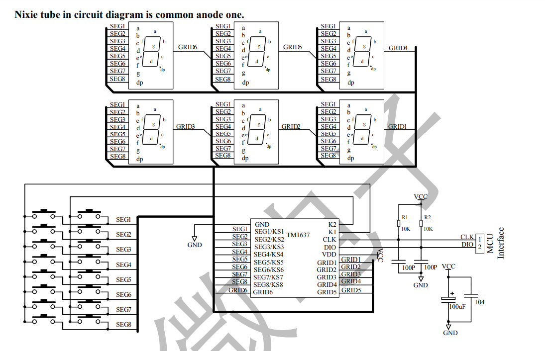
TM1637 communicates with the host using 2 wire protocol, it is very similar to I2C protocol (It matches the wire protocol, but doesn’t have the I2C address) but not exactly same. If you have full control on the I2C hardware of the host controller, it might be possible to use the I2C hardware instead of bitbanging the data. Most of the libraries available uses bitbang instead of I2C hardware. It supports maximum clock frequency of 500 KHz.
Wire protocol
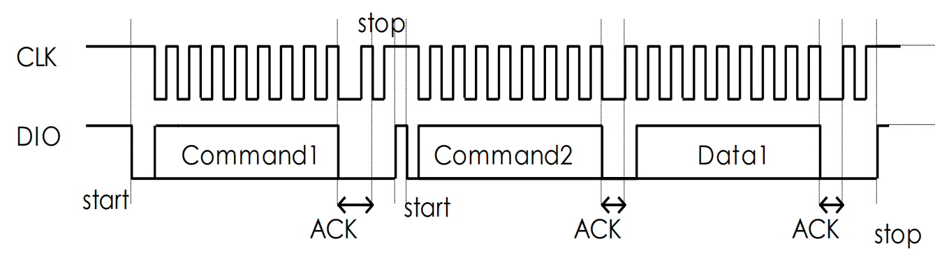
Pulling the Data line (DIO) down while the clock is high indicates start bit and pulling it up while the clock is high indicates stop bit. while sending data, the data line need to change its state when the clock is low, the chip will read the data line when the clock moves from low to high. When the communication is initiated the first byte will act as mode/data command which will tell the driver on how to interpret the incoming bytes.
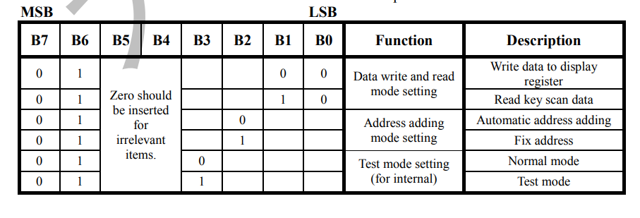
The driver has 6 8-bit display registers ( 0xC0- 0xC5 ) for holding state of each LED. Data can be set in each register individually(Fixed address mode) or can be written to the consecutive set of registers (Automatic address mode).
Fixed address mode
In fixed address mode, we need to send 3 bytes to write data to any one display register.
<mode/data command> <address> <display register data>
mode command tells the driver how interpret the incoming data. For example if we want to write 0x3F (represents decimal 0 on 7-segment display) to 0xC0 register (first display register), we need to send following byte stream on the wire.
0x44 0xC0 0x3F
Automatic address mode
In automatic address mode, we just send the first display register address, then send as many bytes as there are register from the given register offset. For example to write 1234 decimals to a 4 digit 7 segment display we need to send the following byte stream.
0x40 0xC0 0x06 0x5B 0x4F 0x66
Display control
The driver also lets us control the brightness of the display, it supports 8 levels of brightness. To set brightness we need to two bytes.
<mode/data command> <display command>
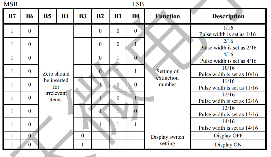
For example to set the display at ~62% brightness, we need to send following byte stream. The second byte values ranges from (0x88 to 0x8F).
0x40 0x8B
We can also switch off the display by sending following byte stream.
0x40 0x80
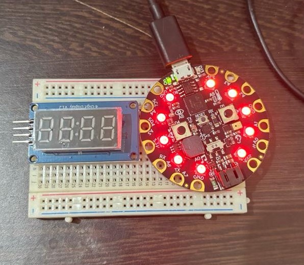
Connections
express board – display board
3.3V – VCC
GND – GND
A4 – CLK
A5 – DIO
display board has onboard pullups on clock and data lines, so no external pull ups are required.
Code
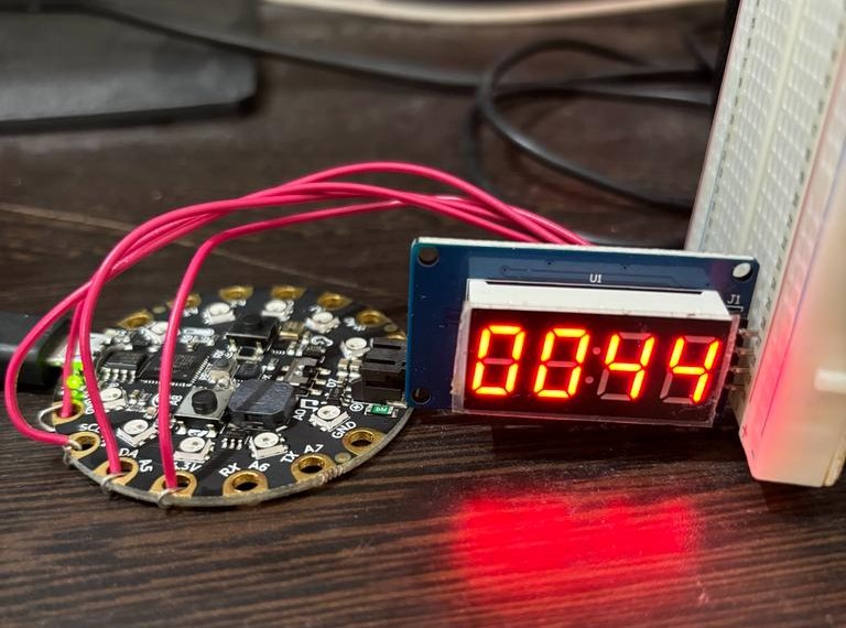
Open mu editor and create/open code.py file and copy the following code into it and save the file. (Code is adopted from TM1636 library). You can see that the 7 segment display will start counting numbers.
import time
import board
import digitalio

_CMD1   = 0x40      # data command
_CMD2   = 0xC0      # address command
_CMD3   = 0x80      # display control command
_DSP_ON = 0x08      # display on
_DELAY  = 0.000010  # 10us delay between clk/dio pulses
_MSB    = 0x80      # decimal point or colon depending on your display
clk = board.A4
dio = board.A5
# 0-9
_SEGMENTS = bytearray(b'\x3F\x06\x5B\x4F\x66\x6D\x7D\x07\x7F\x6F')
_clk = digitalio.DigitalInOut(clk)
_clk.direction = digitalio.Direction.OUTPUT
_clk.value     = 0
_dio = digitalio.DigitalInOut(dio)
_dio.direction = digitalio.Direction.OUTPUT
_dio.value     = 0
_brightness = 7
time.sleep(_DELAY)

def _start():
    _dio.value = 0
    time.sleep(_DELAY)
    _clk.value = 0
    time.sleep(_DELAY)

def _stop():
    _dio.value = 0
    time.sleep(_DELAY)
    _clk.value = 1
    time.sleep(_DELAY)
    _dio.value = 1

def _write_byte(b):
    for i in range(8):
      _dio.value = (b >> i) & 1
      time.sleep(_DELAY)
      _clk.value = 1
      time.sleep(_DELAY)
      _clk.value = 0
      time.sleep(_DELAY)
    _clk.value = 0
    time.sleep(_DELAY)
    _clk.value = 1
    time.sleep(_DELAY)
    _clk.value = 0
    time.sleep(_DELAY)

def _write_data_cmd():
    # automatic address increment, normal mode
    _start()
    _write_byte(_CMD1)
    _stop()

def _write_dsp_ctrl():
    # display on, set brightness
    _start()
    _write_byte(_CMD3 | _DSP_ON | _brightness)
    _stop()

def brightness(val=7):
    _brightness = val
    _write_data_cmd()
    _write_dsp_ctrl()

def write( segments, pos=0):
    _write_data_cmd()
    _start()

    _write_byte(_CMD2 | pos)
    for seg in segments:
      _write_byte(seg)
    _stop()
    _write_dsp_ctrl()

def encode_char(char):
    o = ord(char)
    if o >= 48 and o <= 57:
      return _SEGMENTS[o-48] # 0-9
    raise ValueError("Character out of range: {:d} '{:s}'".format(o, chr(o)))

def encode_string(string):
    segments = bytearray(len(string))
    for i in range(len(string)):
      segments[i] = encode_char(string[i])
    return segments

def showNumber(num):
    string = '{:04d}'.format(num)
    print(string)
    write(encode_string(string))

if __name__ == "__main__":
  print("TM1637 interface")
  _write_data_cmd()
  _write_dsp_ctrl()
  count = 0
  while True:
    count = count + 1
    print(count)
    showNumber(count)
    t = time.localtime()
    time.sleep(10)


