Setting up ESP32-CAM board
ESP32-CAM is an inexpensive ESP32 based video processing board. It comes with ESP32-S AI-Thinker module and 2MP OV2640 camera. Seems the board is designed such that It can be included in the final product (by directly placing the board on the product PCB). It doesn’t have an on board USB-UART converter, so programming it is bit cumbersome. We have to use an external USB-UART board and put the ESP32-CAM board in download mode manually. We can’t power it from PC USB source, as it requires a power source capable of supplying 5v/2A when the camera is operating.
Features
ESP32-S AI-Thinker WiFi/BT module
4MB Flash & 8MB PSRAM
SD Card slot
2MP OV2640 camera
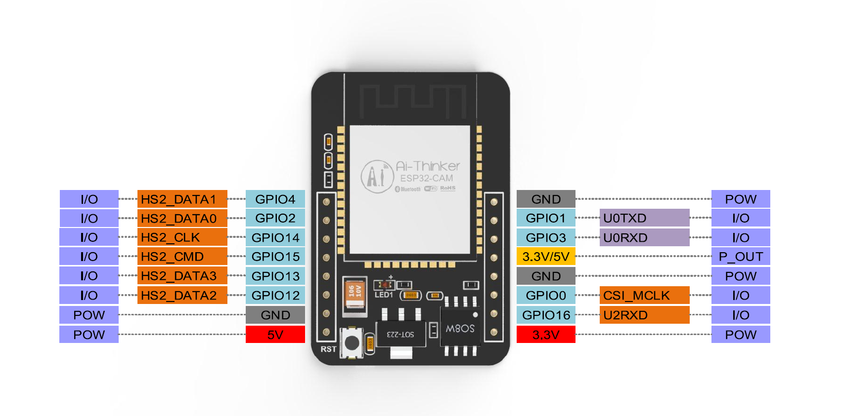
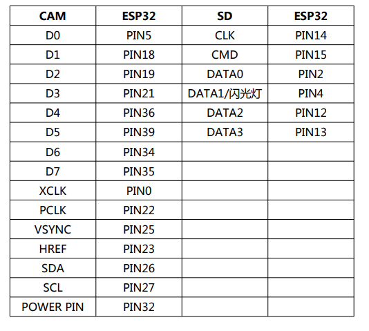
ESP32-CAM Pin out
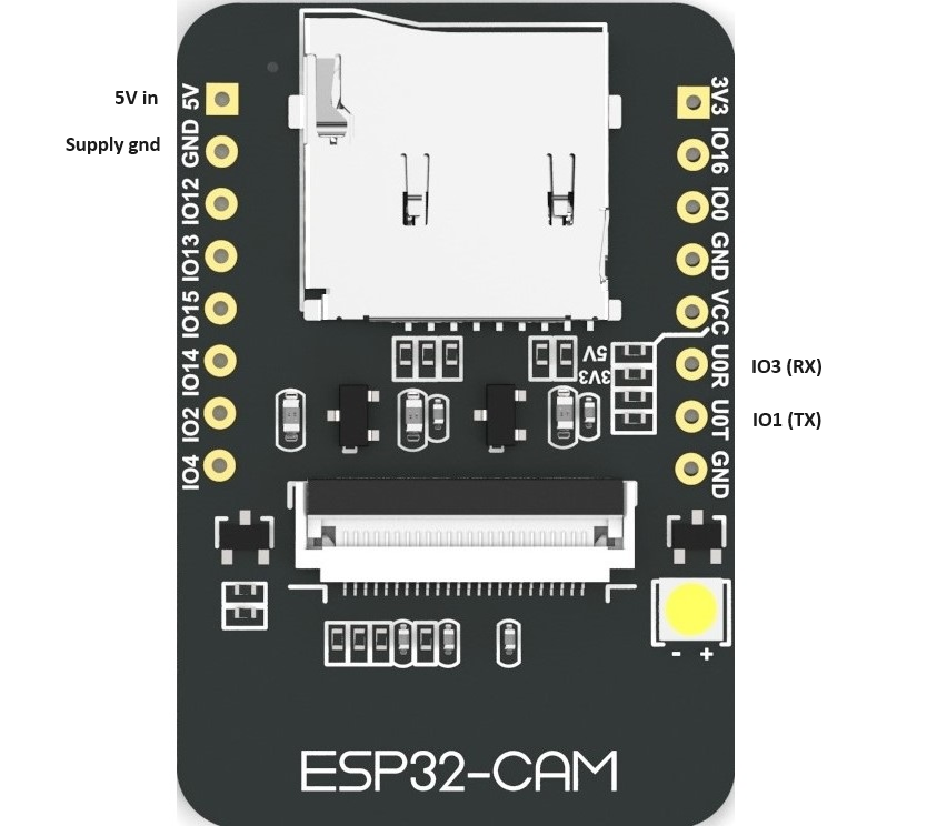
If we use the on board SD card, then there aren’t many IOs left for application usage. Board uses all the available IOs for the camera and SD card interfaces. Only free IOs are IO1 and IO3 which we need for the programming of the board. If there is need to communicate with the external host controller, UART seems to be the only way available. You can checkout the board schematic here.
Connecting USB-UART Connector (FTDI board)
The ESP32-CAM board doesn’t have an on-board USB-UART converter, so we have to connect and external one (please make sure put the converter in 3v3 mode).
ESP32 – FTDI Board
U0T – Rx
U0R – Tx
Gnd – Gnd
To put the board in programming mode, connect IO0 to gnd and reset the board. This connection needs to be removed once program is loaded to the board.
Programming ESP32-CAM board
if you haven’t installed ESP32 boards, follow this guide and install ESP32 support. Then select “AI Thinker ESP32-CAM” board from Tools -> Boards -> ESP32 Arduino. Once the board is selected, select the right COM port and load the following code (the code is adopted from the arduino examples, you can also load the example itself). Please note to update the WiFi details in the code before loading it.
#include "esp_camera.h"
#include <WiFi.h>

#define CAMERA_MODEL_AI_THINKER
#include "camera_pins.h"

// ===========================
// Enter your WiFi credentials
// ===========================
const char* ssid = "****";
const char* password = "****";

void startCameraServer();
void setupLedFlash(int pin);

void setup() {
  Serial.begin(115200);
  Serial.setDebugOutput(true);
  Serial.println();

  camera_config_t config;
  config.ledc_channel = LEDC_CHANNEL_0;
  config.ledc_timer = LEDC_TIMER_0;
  config.pin_d0 = Y2_GPIO_NUM;
  config.pin_d1 = Y3_GPIO_NUM;
  config.pin_d2 = Y4_GPIO_NUM;
  config.pin_d3 = Y5_GPIO_NUM;
  config.pin_d4 = Y6_GPIO_NUM;
  config.pin_d5 = Y7_GPIO_NUM;
  config.pin_d6 = Y8_GPIO_NUM;
  config.pin_d7 = Y9_GPIO_NUM;
  config.pin_xclk = XCLK_GPIO_NUM;
  config.pin_pclk = PCLK_GPIO_NUM;
  config.pin_vsync = VSYNC_GPIO_NUM;
  config.pin_href = HREF_GPIO_NUM;
  config.pin_sscb_sda = SIOD_GPIO_NUM;
  config.pin_sscb_scl = SIOC_GPIO_NUM;
  config.pin_pwdn = PWDN_GPIO_NUM;
  config.pin_reset = RESET_GPIO_NUM;
  config.xclk_freq_hz = 20000000;
  config.frame_size = FRAMESIZE_UXGA;
  config.pixel_format = PIXFORMAT_JPEG; // for streaming
  //config.pixel_format = PIXFORMAT_RGB565; // for face detection/recognition
  config.grab_mode = CAMERA_GRAB_WHEN_EMPTY;
  config.fb_location = CAMERA_FB_IN_PSRAM;
  config.jpeg_quality = 12;
  config.fb_count = 1;

  // if PSRAM IC present, init with UXGA resolution and higher JPEG quality
  //                      for larger pre-allocated frame buffer.
  if(config.pixel_format == PIXFORMAT_JPEG){
    if(psramFound()){
      config.jpeg_quality = 10;
      config.fb_count = 2;
      config.grab_mode = CAMERA_GRAB_LATEST;
    } else {
      // Limit the frame size when PSRAM is not available
      config.frame_size = FRAMESIZE_SVGA;
      config.fb_location = CAMERA_FB_IN_DRAM;
    }
  } else {
    // Best option for face detection/recognition
    config.frame_size = FRAMESIZE_240X240;
  }

  // camera init
  esp_err_t err = esp_camera_init(&config);
  if (err != ESP_OK) {
    Serial.printf("Camera init failed with error 0x%x", err);
    return;
  }

  sensor_t * s = esp_camera_sensor_get();
  // initial sensors are flipped vertically and colors are a bit saturated
  if (s->id.PID == OV3660_PID) {
    s->set_vflip(s, 1); // flip it back
    s->set_brightness(s, 1); // up the brightness just a bit
    s->set_saturation(s, -2); // lower the saturation
  }
  // drop down frame size for higher initial frame rate
  if(config.pixel_format == PIXFORMAT_JPEG){
    s->set_framesize(s, FRAMESIZE_QVGA);
  }

  setupLedFlash(LED_GPIO_NUM);

  WiFi.begin(ssid, password);
  WiFi.setSleep(false);

  while (WiFi.status() != WL_CONNECTED) {
    delay(500);
    Serial.print(".");
  }
  Serial.println("");
  Serial.println("WiFi connected");

  startCameraServer();

  Serial.print("Camera Ready! Use 'http://");
  Serial.print(WiFi.localIP());
  Serial.println("' to connect");
}

void loop() {
  // Do nothing. Everything is done in another task by the web server
  delay(10000);
}
After loading the code, open serial monitor you should see an IP on which the camera interface will be available.
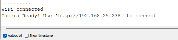
enter the URL in the browser and you should see the following interface. Once you click on “Start stream” button live video feed will appear on the screen in couple of seconds (If you see a chrome warning about security, please click on “continue to site” button).
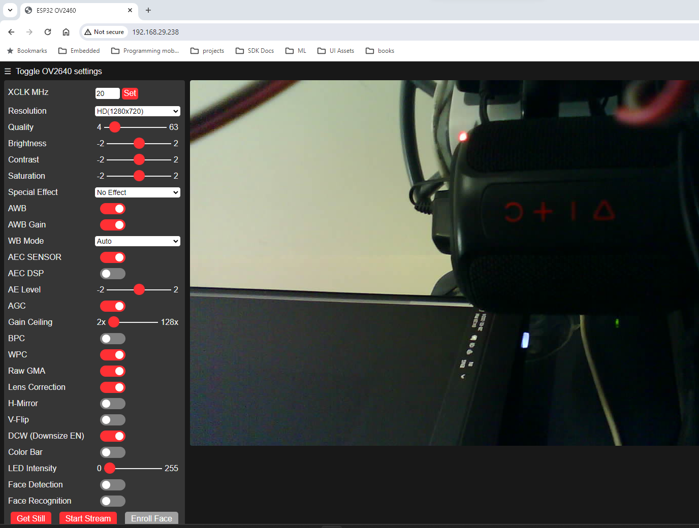
We can also capture a still image by clicking on the “Get Still” button.


